
How does a flex circuit differ from a traditional rigid PCB
3 min readflex circuit differ from a traditional rigid PCB
When you need to connect devices and circuitry in a product with limited space, flex circuits offer wiring solutions that fit where rigid boards cannot. These circuits can be single-sided, double-sided, or multi-layered. The best choice will depend on the specific needs of your application.
A flex circuit’s core is made of flexible polymer rather than the standard fiberglass used in traditional PCBs. The majority of flex circuits are made with a high-quality polyimide (PI) film that stays flexible even after thermosetting. Unlike most thermosetting resins, which become rigid upon heating, PI film retains its flexibility, which is crucial for the flex circuit’s ability to bend and flex without damage or failure. The flex circuit’s conductive copper foil is then embedded in the PI, and the entire assembly is covered with a thin layer of epoxy or another thermoset material. The copper is also plated with an appropriate surface finish to reduce resistance, add strength, and make the signal lines visible for easier soldering.
Unlike rigid PCBs, which use thicker dielectric substrates that increase weight and take up space, flex circuits feature the thinnest dielectric materials available, which allows them to shrink down in size and weigh less. This reduction in package size and weight makes flex circuit ideal for products like cameras, drones, and wearables.
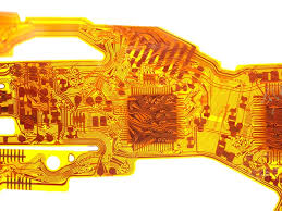
How does a flex circuit differ from a traditional rigid PCB
The flexibility of a flex circuit also means that it can be folded and bent to fit inside the molded plastic product shape, allowing it to conform to the product’s unique design. This helps to save time and money during manufacturing by eliminating the need for extra connectors and cables. It also makes the final product more aesthetically pleasing, which can be important in consumer electronics and medical applications.
A flex circuit’s impedance—which refers to how much electricity travels down a trace and how well it matches up with other signals on the board—can be modified to match specific application requirements. To achieve this, the thickness of the copper traces, the distance between the trace and other signal traces, and the reference plane layers must be carefully chosen. Choosing the right surface finishes is also important to protect against moisture and corrosion, while still offering a solderable connection.
Many flex circuits use surface mount technology to simplify the manufacturing process by eliminating the need for point-to-point wire connections between components. This can help to save time and cost by reducing the number of connections, but if you choose to include a complex SMT layout with tight tolerances, it is necessary to incorporate mechanical stiffeners along the flex areas to support them.
Pad fillets are also important for flex circuits, as they improve the etch yield and material strength while preventing stress fractures or tears. A flex circuit should also include a tear relief slot and large corner radius to prevent premature failure. It’s also recommended to include shielding on the flex circuit’s outer layer and add a reference plane layer and/or blind or buried vias.
